| Return to previous page |
|
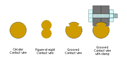
Ordinary electrical wire is circular in cross-section but this is difficult to suspend from overhead fittings in such a way that the contact device of the tramcar, pressing on the underside, does not foul the attachment points.
On the earliest tramways, the suspension 'ears' were soldered to the top and sides of the circular wire.

Where soldering was undesirable, 'mechanical ears' were used but a circular wire restricted their area of grip. Wires of non-circular cross-section were developed so that mechanical attachment could be made to the upper side without being fouled by the contact device running on the lower side.


|
|
|
|
The electrical resistance of overhead contact wire can be found from the following tables:
(The wire gauges follow historic tramway practice although present day manufacturers will often quote them in metric units.)
|
|
|
|
|
|
||||
|
|
|
|
|
Lbs./mile |
|
|
||
|
0000000 S.W.G. |
|
|
|
|
|
|
|
|
|
|
000000 S.W.G. |
|
|
|
|
|
|
|
|
|
|
0000 B&S |
|
|
|
|
|
|
|
|
|
|
00000 S.W.G. |
|
|
|
|
|
|
|
|
|
|
000 B&S |
|
|
|
|
|
|
|
|
|
|
0000 S.W.G. |
|
|
|
|
|
|
|
|
|
|
000 S.W.G. |
|
|
|
|
|
|
|
|
|
|
00 B&S |
|
|
|
|
|
|
|
|
|
|
00 S.W.G. |
|
|
|
|
|
|
|
|
|
|
0 B&S |
|
|
|
|
|
|
|
|
|
|
0 S.W.G. |
|
|
|
|
|
|
|
|
|
|
|
|
|
|
|
||||
|
|
|
|
|
Lbs./mile |
|
|
||
|
0000000 S.W.G. |
|
|
|
|
|
|
|
|
|
|
000000 S.W.G. |
|
|
|
|
|
|
|
|
|
|
00000 S.W.G. |
|
|
|
|
|
|
|
|
|
|
000 B&S |
|
|
|
|
|
|
|
|
|
|
0000 S.W.G. |
|
|
|
|
|
|
|
|
|
|
000 S.W.G. |
|
|
|
|
|
|
|
|
|
|
00 B&S |
|
|
|
|
|
|
|
|
|
|
00 S.W.G. |
|
|
|
|
|
|
|
|
|
|
0 S.W.G. |
|
|
|
|
|
|
|
|
|
Supposing a tramcar is at one end of a 1 Km length of 000 S.W.G. overhead copper wire, the sub station is supplying 750 volts to the other end. Calculate the voltage available to the tram when:
From the above tables, the resistance of 1
Km of 000 S.W.G. copper wire is 0.2461 ohms
The current drawn through the wire = 0 Amps
Ohm's Law states that the voltage dropped equals current x resistance
The voltage dropped in the
wire in this case = 0 x 0.2461 = 0 volts
so the voltage available to the tram = 750 - 0 =
750 volts
Now the current through the wire is 200 Amps and its resistance is 0.2461 ohms
Ohms law says the voltage drop will be 200 x 0.2461 = approx 50 volts
So the voltage available to the tram will be 750 - 50 = 700 volts
The voltage difference along
the wire will be 100 x 0.2461 = approx 25 volts
but the current is now flowing from the tram to the sub-station
end of the wire, the opposite direction from before. The voltage
difference is now the other way around, it is a voltage gain.
The voltage at the tram will now be 750 + 25 = 775 volts
This is not magic, getting more than we started with. It shows that the tram is returning to the system, some of the energy it took when it accelerated
| Return to previous page |
|