| Return to previous page |
|
To make electrical contact with the overhead wire, the tramcar is fitted with a current collecting device. In the earliest experiments, this was in the form of a small wheeled trolley which ran on the top of a pair of wires, towed along by the tramcar and feeding current to it through a cable. The tram which obtained its power in this way was known as a 'Trolley Car', later abbreviated to 'Trolley' and used in the U.S.A. as the general term for any type of railed street-running vehicle.
The development of the present-day system of a spring-loaded device pressing upwards on the underside of a suspended wire is credited to Frank Sprague of the U.S.A.
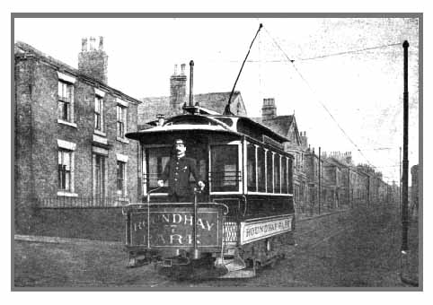
The first tramway of this type in Britain was built by the Thompson-Houston International Electric Company and was officially inaugurated in the Roundhay district of Leeds on October 29, 1891.
This formed the basis for many other systems throughout the British Isles, nearly all of them initially using the trolley pole with contact-wheel device shown in the illustration.
With the wheel assembly fixed rigidly to the pole, the contact wire had to be over the centre of the track so that the wheel did not run 'crab-wise' and cause excessive wear. The development of the swivelling 'globe' trolley head allowed the contact wire to be displaced to one side of the track, the wheel swivelling about a vertical-axis pivot so as to line up with the wire. This was advantageous because it allowed greater choice in the positioning of the wire. By running it nearer the kerb, shorter overhanging bracket arms could be fitted to the tram poles, economising in materials and improving the appearance of the structure. Where open top decks were used, the contact wire could be safely out of reach of passengers, especially where a low overbridge was encountered.
If the proposed system for Bath were to be extended along the Avon Valley Railway tracks, the use of a side-running wire system would be advantageous. The track would be shared with the steam locomotives which presently use it; placing the wire to one side would remove it, and its insulators, from the direct blast of the locomotive chimney and the corrosive effects of the fumes. More importantly the side placing of the wire would put it out of reach of train crews. This would be an important safety factor if, for instance, a tall fireman of a steam locomotive were to perch on a tender-full of coal and wave a shovel.
As tramway speeds increased, the wheel on the end of the trolley pole, which made contact with the wire, was subjected to considerable strain. At 50 mph it could be revolving at speeds up to 1,700 rpm. whilst carrying currents of over 100 amps. The wheels and bearings needed constant maintenance and repair. Any kinks in the overhead wire were liable to throw the wheel off the wire and, in the case of side-running systems, the tendency was for the direction of pull of the trolley pole to be to one side, making de-wirement more likely.
If the trolley wheel became 'de-wired' it could fly up in the air and become entangled in the support wires. The trolley heads were easily detachable to prevent damage to the overhead structure if this occurred, a piece of rope preventing the sizeable chunk of detached metal from falling on unwary road users. (A falling trolley head has been known to punch a hole through the roof of a saloon car when the restraining rope snapped)
A sliding contact device was developed to overcome the disadvantages of the trolley-wheel system. It made use of the ability of a carbon rubbing surface to give good current distribution over the area of contact and reduce problems from arcing and pitting of the wire.
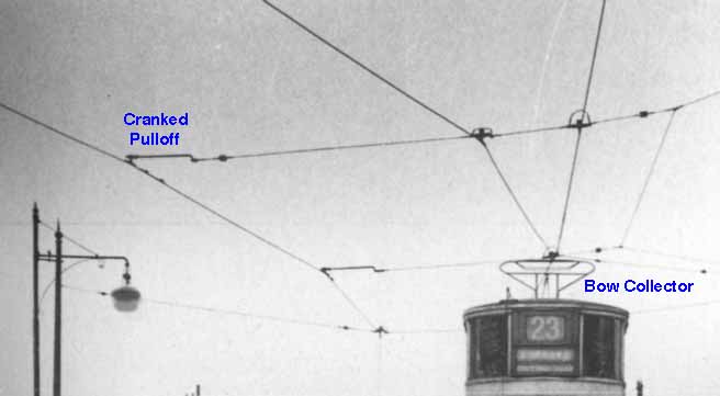
The bow collector, with a wide carbon rubbing strip, was much less critical of the positioning of the contact wire. This could be used to advantage by setting up the wire around curves in longer straight sections, requiring less overhead hardware. The disadvantge was that the support wires had to be kept well clear of the width of the bow and larger 'cranked' pulloff insulators were necessary in certain places.
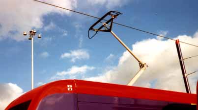 Pantograph
Continental practice has been to use a pantograph, a trellis device, for supporting the contact bow. Nowadays, an elegant, single-support variation of the pantograph is very popular. It is carefully designed to maintain good contact with the wire at all speeds with the minimum of wear and to be unaffected by aerodynamic forces.
There is one condition, however, which precludes
the use of a sliding contact current collector - the use of open-topped
vehicles.
The edge of the carbon contact strip can occasionally flake away
and drop as small particles of hot carbon onto the roof of the
tram or the roadway. By the time these reach the road, they are
harmless; but if such particles were to drop, whilst still hot,
onto passengers sitting on an open top deck, there would be numerous
complaints.
To allow for the possibility of using replica
or actual historic vehicles as a tourist attraction, the overhead
system for Bath should be designed so as to accommodate both types
of current collector.
| Return to previous page |
|