
|
|
|
D.C. POWER STATIONS - Steam Engines
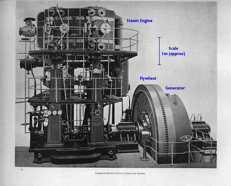
In 1904, when the Bath Electric Tramways power station was constructed, steam turbines were still struggling to gain acceptance in power stations of this size. The BET station was designed for the tried and tested technology of reciprocating steam engines.
The three main generators were powered by double-acting reciprocating engines made by Yates and Thom. They were compound engines with Corliss valve gear, a design which gave high efficiency.
Reciprocating Steam Engines
In a reciprocating engine, a piston is driven along a cylinder by
pressure on one of its faces. This motion is converted to rotation by
a crank. As the crank continues to rotate, the piston returns to its
starting position and repeats the cycle. This to-and-fro motion gives
rise to the description 'reciprocating' as opposed to a continuously
rotating engine such as a turbine.
Double-acting
When the piston reaches the end of its first travel, the power
stroke, the pressure in the cylinder is released and the piston can
be driven back by the continuing motion of the crank. If the engine
has more than one cylinder, the return stroke of one piston is
arranged to occur during the power stroke of another, and smooth
continuous rotation results.
If the engine has only one cylinder, a large flywheel can be used to keep the crank rotating during the return stroke, but the speed of the engine will be uneven as the flywheel is alternately powered and 'coasted'. Alternatively, the piston can be driven back by steam pressure on the opposite side from before. The piston is therefore powered in both directions and is said to be 'double-acting'.
Compounding
As the piston reaches the end of its travel, any residual steam
pressure must be released from the cylinder before it can be driven
back by steam from the opposite end. When the initial supply of steam
was at high pressure, the released steam would still have sufficient
pressure to be useful. It could be supplied to a second cylinder,
coupled to the first, and allowed to do some more work with the
remainder of its energy. An engine which uses the steam twice in this
way is known as a 'compound' engine.
Because the second cylinder is designed to work with steam which has already expanded, it is of considerably larger volume than the high pressure cylinder and a larger surface area piston is available to extract energy from the lower pressure steam.
Corliss valves
Because high pressure steam expands, there is no need to continue
allowing steam into the cylinder to fill the extra space as the
piston travels through its stroke. A single 'shot' of steam at the
start of the stroke is all that is needed.
The valves which allow the steam into the cylinder are a potential point of energy wastage. If they open and shut gradually, the steam flow will be restricted and expansion will occur in the valves instead of in the cylinders. A quick-acting valve is needed, especially one with a cut-off timing which can be automatically varied to suit the load on the engine.
By 1904, the Corliss valve was considered to offer the greatest efficiency. It worked rather like a domestic gas tap, with a rotating 'plug' inside a close-fitting housing. The plug had a large hole bored through it and could be rotated through an angle of 90 degrees to line-up the hole with steam passages in the housing.
Because the steam pressure did not tend to force the valve open or shut (as it did with some other types) the rods which operated the valve could be made relatively light in weight and the whole system operated rapidly and precisely with minimal force.

Click here for a picture of the whole engine
|
|
|